
Boat Gas Gauge Wiring
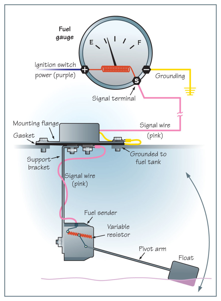
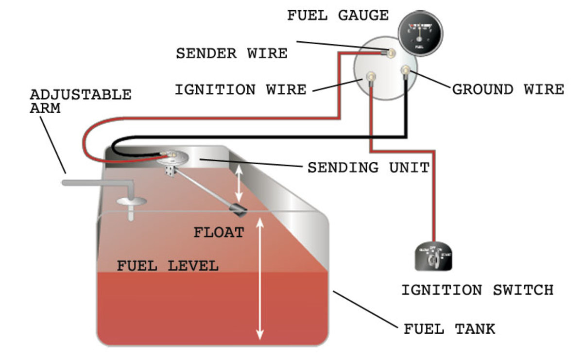
Fuel Sender Unit Fuel Gauge Ground Wire The ground wire is the most basic component within a wiring diagram. This wire provides the electrical link between the tank and the engine, allowing the fuel gauge to get a reading of the amount of fuel in the tank.
[DIAGRAM] 2007 Lcf Fuel Gauge Wiring Diagrams
March 7, 2022 by Wiring Digital A Comprehensive Guide to Understanding The Wiring Diagram For A Boat Fuel Gauge Having a boat fuel gauge is essential for monitoring the level of your boat's fuel. It's important that you know the wiring diagram of your fuel gauge in order to install and maintain it properly.
20 Lovely Marine Fuel Gauge Wiring Diagram
Here is how to wire a fuel gauge: 1. The first step is to disconnect the battery. This is to prevent any accidental shorts while you are working on the wiring. 2. Next, locate the sending unit. This is usually located in the fuel tank, but may be in the engine bay if your car has an external pump. 3.
[DIAGRAM] Car Gas Gauge Diagram
The Basics of Boat Fuel Gauge Wiring Diagrams. Boat fuel gauge wiring diagrams usually show two basic components: the gauge itself and the sending unit. The sending unit is usually mounted on the tank and provides power to the gauge. The gauge is usually mounted on the dashboard or instrument panel, and is where the fuel level is read.

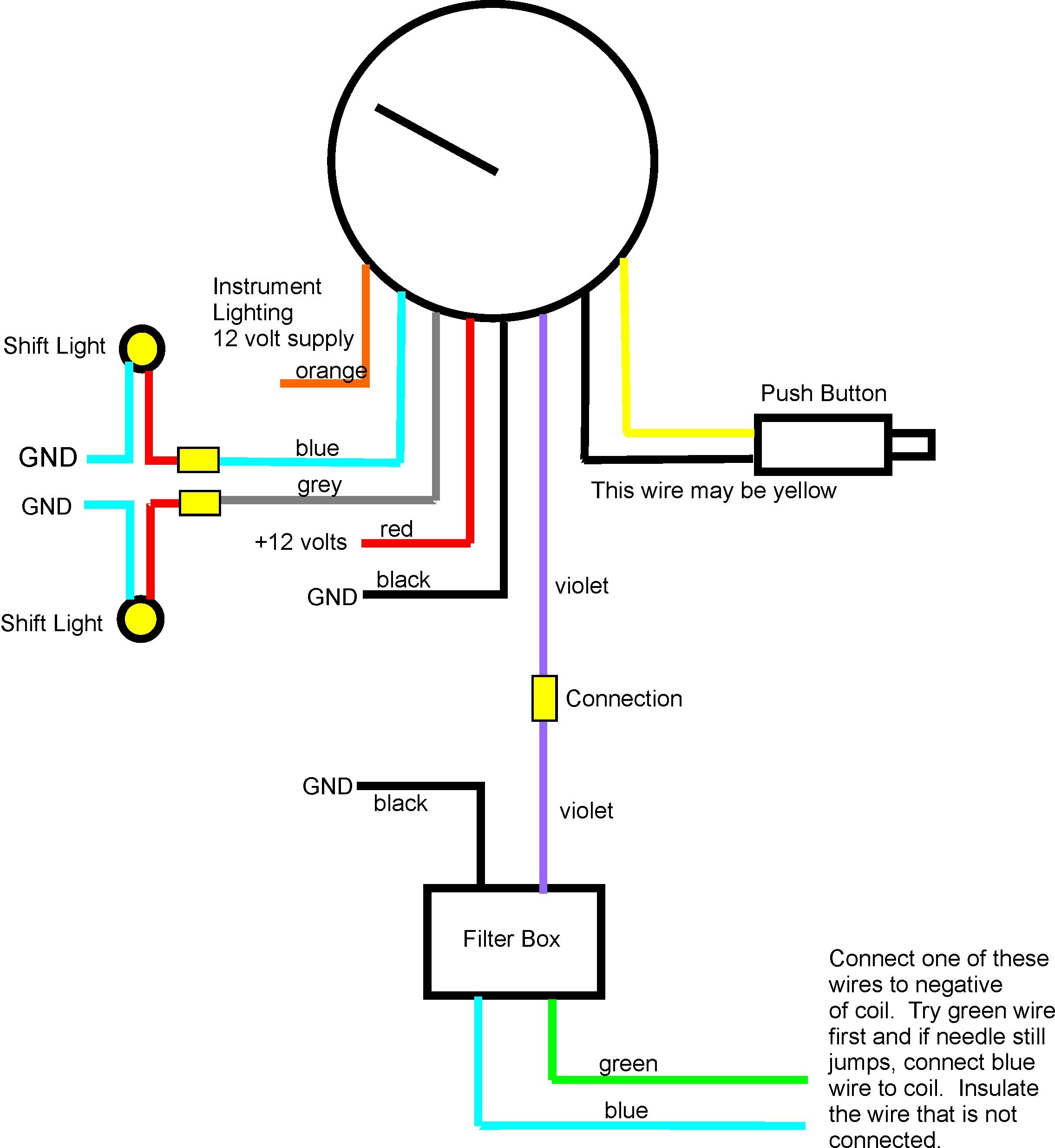
Faria Tachometer Wiring Diagram
The wiring diagram for a fuel gauge on a boat is a simple illustration of the wiring connections that are made from the boat's battery to the fuel gauge. The diagram will show the type of gauge, the type of wiring, and the number of wires that need to be connected to the gauge. It will also show the location of any switches or relays that may.

29 Fuel Gauge Wiring Diagram Chevy Wiring Diagram Info
Does Your Boat Need A New Fuel Tank? Let's Install One! Born Again Boating How to find sending unit Ohm range Boyd Welding How to wire fuel gauge and sending unit complete explanation Old.
Fuel Gauge Wiring Diagram Wiring Diagram
Step 1: Check the wiring diagram then disconnect the battery when you're ready. Step 2: Start connecting the wires to their appropriate terminals. Conclusion A Few Pointers Before You Start Wiring Let's make one thing clear first: Not every fuel gauge has the same installation setup.
19731977 Monte Carlo Fuel Tank Sending Unit 5/16” Line (2 Outlet
Wiring a marine fuel gauge can be a straightforward process if you have a basic understanding of electrical systems. A fuel gauge is an essential component of any boat, as it allows the driver to monitor the amount of fuel remaining in the tank. Proper wiring is crucial to ensure the accuracy of the gauge and to prevent any potential electrical.
Faria Fuel Gauge Wiring
The boat fuel gauge is an essential component of any boat's fuel system, as it allows the captain or operator to monitor the fuel levels in the boat's tank. Understanding how to wire a boat fuel gauge is crucial for proper installation and operation of the gauge. When wiring a boat fuel gauge, it is important to first determine the type of.

️Teleflex Fuel Gauge Wiring Diagram Free Download Gmbar.co
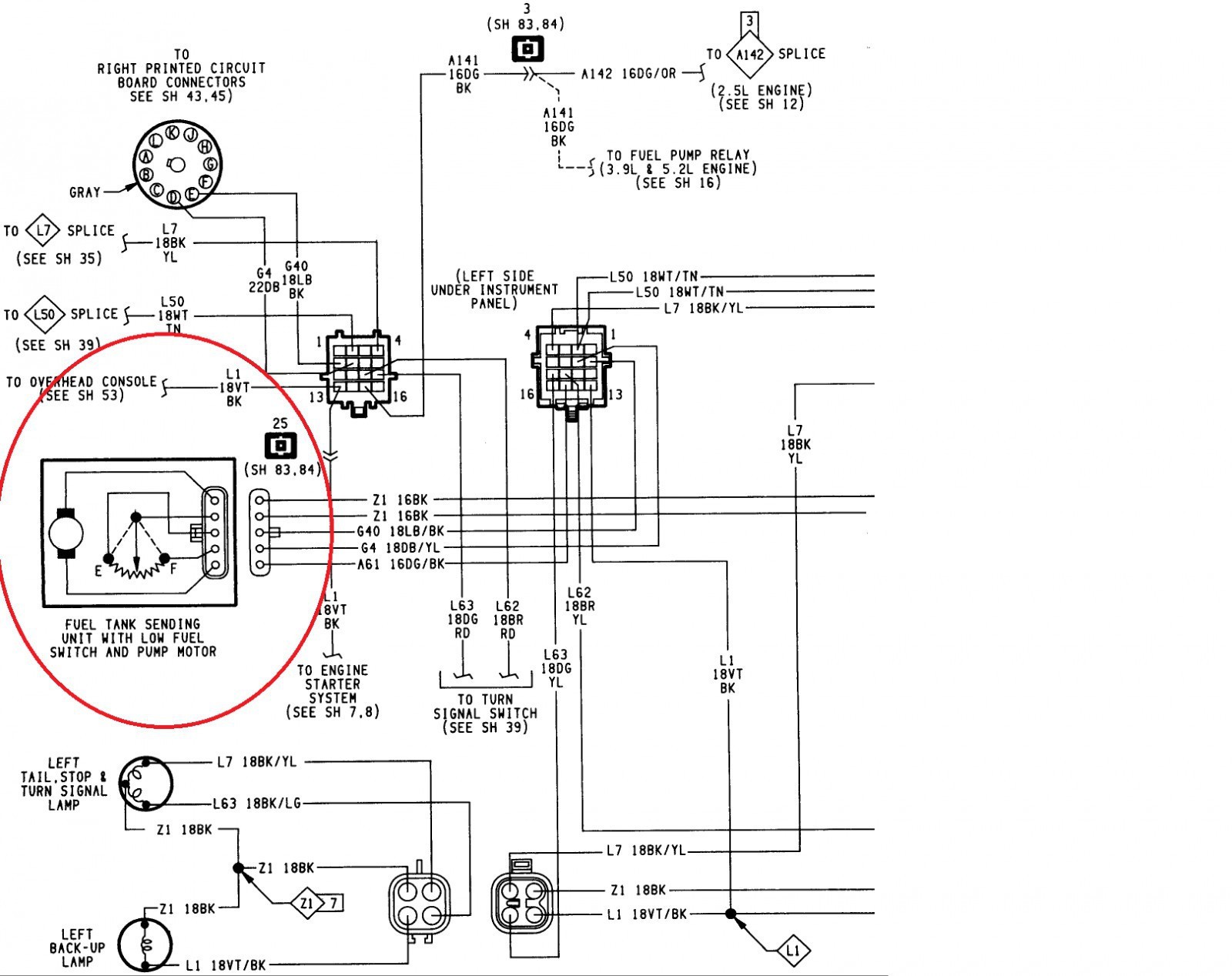
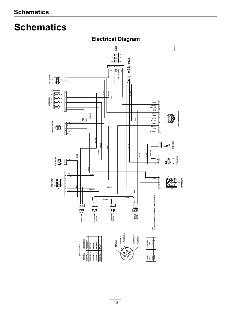
A wiring diagram is a visual representation of the connecting cables and parts used in a system. It is often used for troubleshooting and diagnostics. A wiring diagram for a marine fuel sending unit can be found in the owner's manual or online. This diagram shows the different parts of the fuel sending unit, as well as how they are wired together.

chevy fuel sending unit wiring diagram
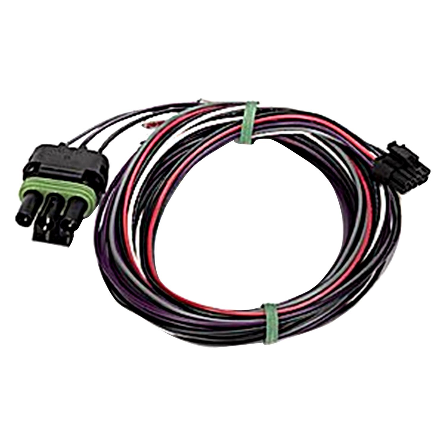
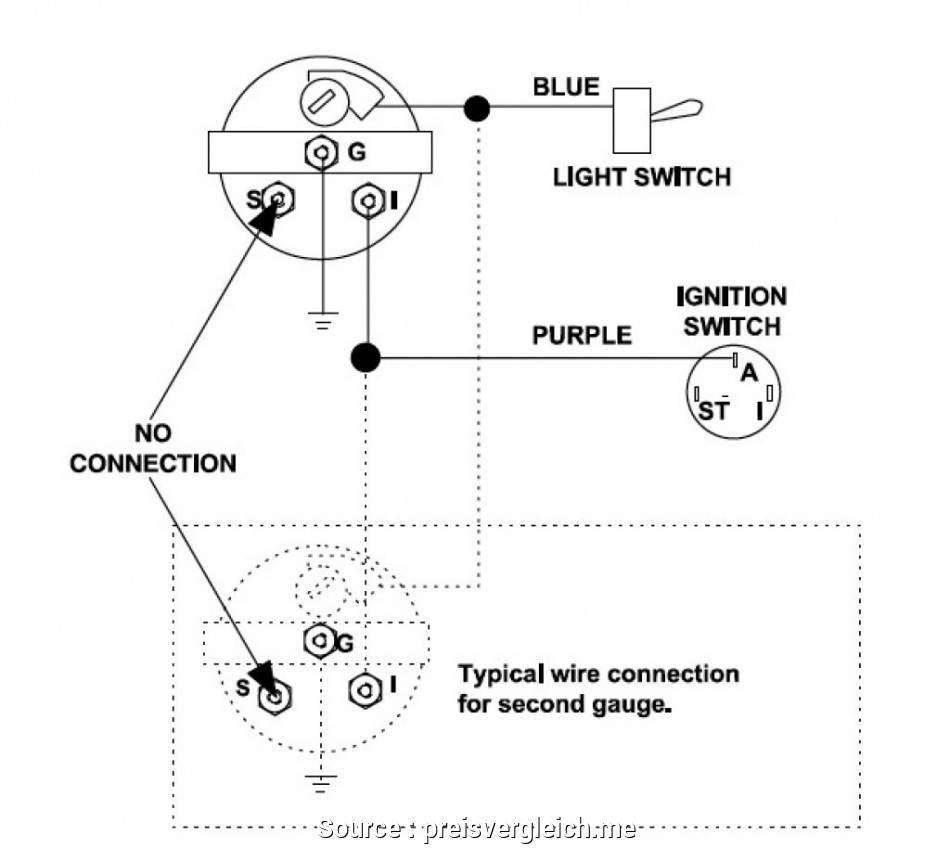
Wiring a fuel gauge is much the same as wiring any other gauge on your boat: one wire comes from the ignition to the instrument, one wire comes from the sensor to the instrument, one wire comes to the instrument light and one wire from the instrument goes to the boat's common ground.
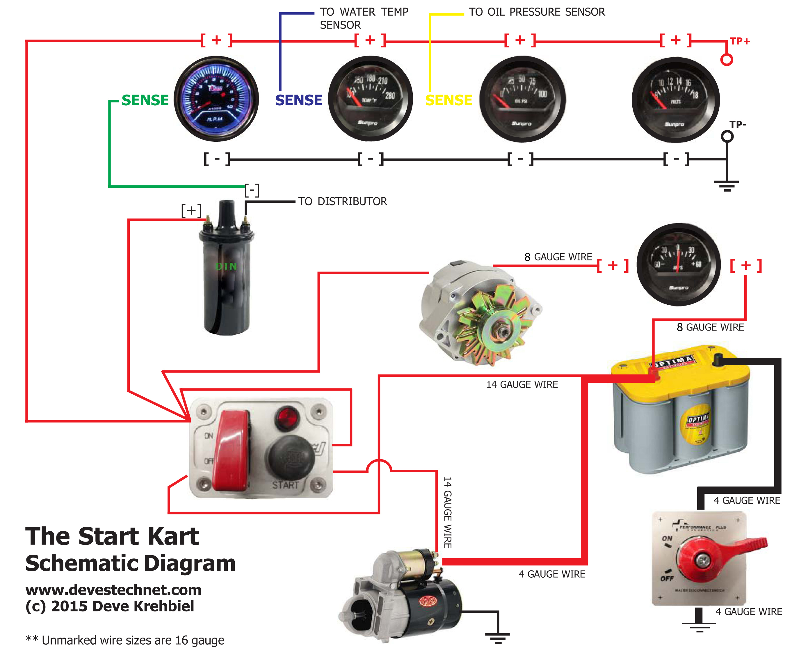
4 Gauge Amp Wiring
The fuel gauge then displays this information on the instrument panel. When it comes to boat fuel gauge wiring, all of these components must be wired correctly in order for the fuel gauge to function properly. This means running a wire from the fuel sending unit to the fuel gauge. Depending on your boat, this may involve some custom wiring.
Autometer Gauge Wiring Diagram Cadician's Blog
Wiring Diagram Wiring Diagram For A Boat Fuel Gauge Wiring Diagram For A Boat Fuel Gauge By Wiring Boards |July 12, 2022 0 Comment Installing a fuel gauge in your boat can be an intimidating task, but with the right information and guidance, it doesn't have to be.
Fuel Sender Unit Wiring Diagram Wiring Expert Group
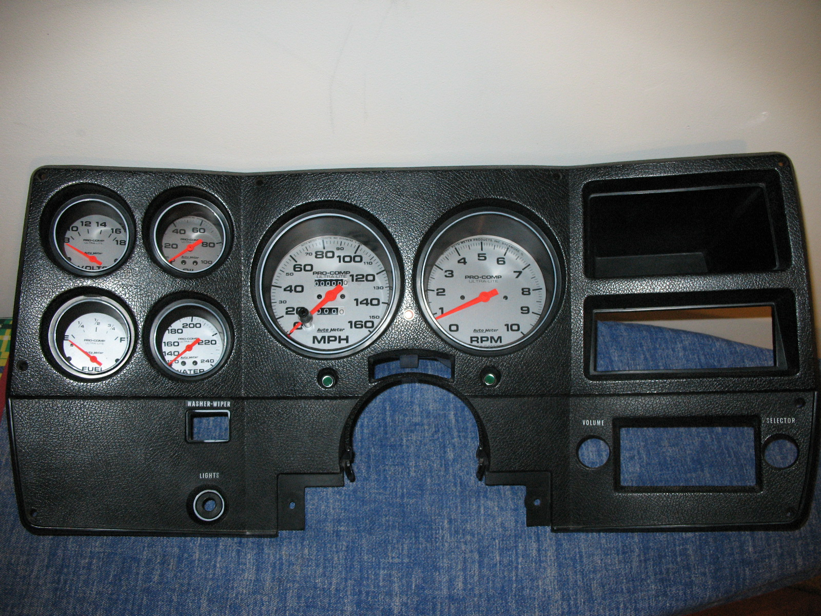
Cut a 2-1/16" diameter hole in the dash and mount the gauge with the back clamp supplied. For connectorized cases be sure to cut a .175" wide by .115" deep notch to accept the key on the case. See detail on next page. (See diagram on the next page for connections) Standard Case Connectorized Case 3.
boat tachometer wiring
The marine fuel sending unit wiring diagram is a critical part of any fuel system. To ensure your boat is running as efficiently as possible, it is important to make sure the wiring is properly installed and connected. This diagram provides an easy-to-follow overview of how the wiring is organized and connected.First, the fuel gauge sends a.
Wiring Boat Fuel Gauge
Recommended Marine Wiring Color Code Direct Current Systems - Under 50 Volts (No diagram required if wiring is in compliance with Tables I and Il) Color Yellow w/Red Stripe (YR) Yellow (Y) Dark Gray (Gy) Brown (Br) Orange (O). Fuel Gauge Sender to Gauge IGNTION SWITCH BLACK BULB SENDER GRND SENDER BATTERY GROUND FUEL .